I hope you will enjoy this video
Sunday, February 27, 2011
Friday, February 18, 2011
Turbine Type Anemometer:
When a rotor attached to a permanent magnet polarized at 90’ to the axis of rotation, and if the rotor is made to rotate due to the fluid velocity V, the rotating magnetic fluid will be cut by the pickup coil generating voltage pulses. The frequency of voltage pulses is proportional to flow rate. Hence the measure of frequency of voltage pulses becomes a measure of flow rate.
The main parts of the turbine meter are as follows:
A turbine wheel (rotor)
A permanent magnet polarized at 90’ to the axis of rotation which is attached to one of the blades of the rotor.
A pickup coil placed external to the meter housing.
A frequency meter or counter attached to the pickup coil.
 The turbine meter is fixed to the pipe carrying the fluid whose volume flow rate is to be measured.
The fluid strikes the blades of the rotor and makes it to rotate. When the rotor rotates, the permanent magnet attached to the rotor blade also rotates, which in turn produces a rotating magnetic field.
Each time the magnet passes the pickup coil, the magnetic flied is being cut generating a voltage pulse. The frequency of voltage pulses is indicated by a frequency meter.
This frequency of voltages pulses becomes a measure of flow rate when calibrated.
The volume flow rate “Q” is given by Q = F/C
Where F = total number of pulses
C = flow Coefficient
They are extensively used in weather stations to measure wind velocity.
They are used to measure water flow in rivers and streams.
Compact models are used to measure flow in tubes and pipes.
Recording and controlling can be done from a distance (telemetry).
High accuracy (error is -/+ 0.5%).
Has good dynamic response.
The pressure drop in the fluid is low.
It is easy to install and maintain.
Error increases if the flow rate is low.
Bearing friction and wear may alter the linear output of this instrument.
For a distance, a straight run of pipe ahead of instrument is required.
Description of Turbine Meter:
The main parts of the turbine meter are as follows:
A turbine wheel (rotor)
A permanent magnet polarized at 90’ to the axis of rotation which is attached to one of the blades of the rotor.
A pickup coil placed external to the meter housing.
A frequency meter or counter attached to the pickup coil.
Operation of Turbine Meter:

The fluid strikes the blades of the rotor and makes it to rotate. When the rotor rotates, the permanent magnet attached to the rotor blade also rotates, which in turn produces a rotating magnetic field.
Each time the magnet passes the pickup coil, the magnetic flied is being cut generating a voltage pulse. The frequency of voltage pulses is indicated by a frequency meter.
This frequency of voltages pulses becomes a measure of flow rate when calibrated.
The volume flow rate “Q” is given by Q = F/C
Where F = total number of pulses
C = flow Coefficient
Applications:
They are extensively used in weather stations to measure wind velocity.
They are used to measure water flow in rivers and streams.
Compact models are used to measure flow in tubes and pipes.
Advantages of turbine Meter:
Recording and controlling can be done from a distance (telemetry).
High accuracy (error is -/+ 0.5%).
Has good dynamic response.
The pressure drop in the fluid is low.
It is easy to install and maintain.
Limitations of turbine meter:
Error increases if the flow rate is low.
Bearing friction and wear may alter the linear output of this instrument.
For a distance, a straight run of pipe ahead of instrument is required.
Wednesday, February 16, 2011
What is a Pitot Tube or Total Pressure Probe
A probe is a device used for point pressure measurement in a flowing fluid. This point measurement of pressure is done to determine fluid flow rate. The most popular probe is the “PITOT TUBE” which is one of the total pressure probes. The Pitot tube measures the combined pressure (static pressure + impact pressure). The pitot tube has one impact opening and eight static openings as shown in the diagram. The impact opening is provided to sense impact pressure and the static opening are provide to sense static pressure.
 The pitot tube is introduced in the fluid flow area where point pressure details is required (which is an indirect measure of flow rate).
The pressure in the outer tube is the static pressure in the line. The total pressure in the inner tube is greater than static pressure. That is, total pressure is the static pressure plus the impact pressure. The differential pressure (P1-P2) is measured using a differential pressure sensor. This differential pressure becomes a measure of flow rate at that point where the pitot tube is present in the flowing fluid.
Pitot tubes are extensively used in laboratories to measure velocity, pressure and flow rates of fluids.
It causes no pressure loss in the flowing fluid.
Pitot tube is cheap and very easy to install.
It is difficult to obtain proper alignment of the pitot tube with flowing direction.
It cannot be used in fluids with suspended solids and impurities.
The fluid velocity should be high in order to get a measurable pressure difference.
Operation of Pitot Tube:

The pressure in the outer tube is the static pressure in the line. The total pressure in the inner tube is greater than static pressure. That is, total pressure is the static pressure plus the impact pressure. The differential pressure (P1-P2) is measured using a differential pressure sensor. This differential pressure becomes a measure of flow rate at that point where the pitot tube is present in the flowing fluid.
Applications of pitot tube
Pitot tubes are extensively used in laboratories to measure velocity, pressure and flow rates of fluids.
Advantages of pitot tube:
It causes no pressure loss in the flowing fluid.
Pitot tube is cheap and very easy to install.
Limitations of Pitot tube
It is difficult to obtain proper alignment of the pitot tube with flowing direction.
It cannot be used in fluids with suspended solids and impurities.
The fluid velocity should be high in order to get a measurable pressure difference.
Monday, February 14, 2011
What is Rotameter or Variable-Area Meter?
Rotameter or Variable Area meter is an instrument used to measure the flow rate of a fluid by using a simple float (let us say a small triangle shaped block) to float in the moving fluid. The operation of the Rotameter is explained in detail below.
The main parts of a Rotameter are as follows:
A tapered transparent glass tube graduated to read flow rate directly.
A float is used whose density is greater than the flowing fluid. The float’s diameter is such that it completely blocks the inlet of the tapered transparent glass tube.
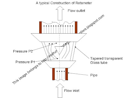
As the fluid whose flow rate is being measured comes and touches the bottom portion of the float blocking the inlet of the tapered transparent glass tube, the float starts to rise when the following happens:
Pressure of flowing fluid + flowing buoyancy is greater than downward pressure due to weight of the float.
When the float rises, an annular space is created between the periphery of the float and the inner wall of the tapered transparent glass tube. This annular space which is concentric opening through which the fluid passes to the other side of the instrument keeps on increasing until the following happens:
(pressure of the flowing fluid) + (fluid buoyancy) = (Downward pressure due to weight of the float)
When this happens, the float stops rising further and stops at a particular position, that is, the float comes to equilibrium.
Thus, increase in flow rate will make the float to rise higher and vice versa. That is, the position of the float becomes a direct indication of flow rate. Hence the tapered transparent glass tube can be graduated suitably by proper calibration to get a direct indication of flow rate by noting the position of the float with respect to the graduations on the tapered tube.
The instrument has to be designed in such a manner so that the effects of changing viscosity and density are minimized leaving only pressure of the flowing fluid as a variable.
Limitations of Rotameter:
They should be installed vertically.
They cannot be used in measurements of moving objects.
The float will not be visible, when colored fluids are used, that is, when opaque fluids are used.
For high pressure and temperature fluid flow measurements, they are expensive.
They cannot be used for fluids containing high percentage of solids in suspension.
Parts of the Rotameter:
The main parts of a Rotameter are as follows:
A tapered transparent glass tube graduated to read flow rate directly.
A float is used whose density is greater than the flowing fluid. The float’s diameter is such that it completely blocks the inlet of the tapered transparent glass tube.
Operation of Rotameter:

As the fluid whose flow rate is being measured comes and touches the bottom portion of the float blocking the inlet of the tapered transparent glass tube, the float starts to rise when the following happens:
Pressure of flowing fluid + flowing buoyancy is greater than downward pressure due to weight of the float.
When the float rises, an annular space is created between the periphery of the float and the inner wall of the tapered transparent glass tube. This annular space which is concentric opening through which the fluid passes to the other side of the instrument keeps on increasing until the following happens:
(pressure of the flowing fluid) + (fluid buoyancy) = (Downward pressure due to weight of the float)
When this happens, the float stops rising further and stops at a particular position, that is, the float comes to equilibrium.
Thus, increase in flow rate will make the float to rise higher and vice versa. That is, the position of the float becomes a direct indication of flow rate. Hence the tapered transparent glass tube can be graduated suitably by proper calibration to get a direct indication of flow rate by noting the position of the float with respect to the graduations on the tapered tube.
The instrument has to be designed in such a manner so that the effects of changing viscosity and density are minimized leaving only pressure of the flowing fluid as a variable.
Application of the Rotameter:
- Rotameter can be used to measure flow rates of corrosive fluids.
- It is particularly useful to measure low flow rates
Advantages of Rotameter:
- Flow conditions are visible.
- Flow rate is a linear function (uniform flow scale).
- Can be used to measure flow rates of liquids, gases and vapours.
- By changing the float, tapered tube or both, the capacity of the Rotameter can be changed.
Limitations of Rotameter:
They should be installed vertically.
They cannot be used in measurements of moving objects.
The float will not be visible, when colored fluids are used, that is, when opaque fluids are used.
For high pressure and temperature fluid flow measurements, they are expensive.
They cannot be used for fluids containing high percentage of solids in suspension.
Friday, February 11, 2011
How to use venturi meter for measuring flow rate
Basic principle:
When a venture meter is placed in apipe carrying the fluid whose flow rate is to be measured, a pressure drop occurs between the entrance and throat of the venturimeter. This pressure drop is measured using a differential pressure sensor and when calibrated this pressure drop becomes a measure of flow rate.
Construction of Venturi meter
The following are the main parts and areas of venture meter:
- The entry of the venture is cylindrical in shape to match the size of the pipe through which fluid flows. This enables the venture to be fitted to the pipe.
- After the entry, there is a converging conical section with an included angle of 19’ to 23’.
- Following the converging section, there is a cylindrical section with minimum area called as the throat.
- After the throat, there is a diverging conical section with an included angle of 5’ to 15’.
- Openings are provided at the entry and throat (at sections 1 and 2 in the diagram) of the venture meter for attaching a differential pressure sensor (u-tube manometer, differential pressure gauge, etc) as shown in diagram.
Operation of venturi meter:

- The fluid whose flow rate is to be measured enters the entry section of the venturi meter with a pressure P1.
- As the fluid from the entry section of venturi meter flows into the converging section, its pressure keeps on reducing and attains a minimum value P2 when it enters the throat. That is, in the throat, the fluid pressure P2 will be minimum.
- The differential pressure sensor attached between the entry and throat section of the venturi meter records the pressure difference(P1-P2) which becomes an indication of the flow rate of the fluid through the pipe when calibrated.
- The diverging section has been provided to enable the fluid to regain its pressure and hence its kinetic energy. Lesser the angle of the diverging section, greater is the recovery.
Application:
- It is used where high pressure recovery is required.
- Can be used for measuring flow rates of water,gases,suspended solids, slurries and dirty liquids.
- Can be used to measure high flow rates in pipes having diameters in a few meters.
Advantages of venturi meters
- Less changes of getting clogged with sediments
- Coefficient of discharge is high.
- Its behaviour can be predicted perfectly.
- Can be installed vertically, horizontally or inclinded.
Limitations
- They are large in size and hence where space is limited, they cannot be used.
- Expensive initial cost, installation and maintenance.
- Require long laying length. That is, the veturimeter has ti be proceeded by a straight pipe which is free from fittings and misalignments to avoid turbulence in flow, for satisfactory operation. Therefore, straightening vanes are a must.
- Cannot be used in pipes below 7.5cm diameter.
Sunday, February 6, 2011
Flow Measurement Using Flow Nozzle:
Basic Principle of Flow Nozzle:
When a flow nozzle is placed in a pipe carrying whose rate of flow is to be measured, the flow nozzle causes a pressure drop which varies with the flow rate. This pressure drop is measured using a differential pressure sensor and when calibrated this pressure becomes a measure of flow rate.
Description of Flow Nozzle:

The main parts of flow nozzle arrangement used to measure flow rate are as follows:
- A flow nozzle which is held between flanges of pipe carrying the fluid whose flow rate is being measured. The flow nozzle’s area is minimum at its throat.
- Openings are provided at two places 1 and 2 for attaching a differential pressure sensor (u-tube manometer, differential pressure gauge etc.,) as show in the diagram.
Operation of flow Nozzle:

- The fluid whose flow rate is to be measured enters the nozzle smoothly to the section called throat where the area is minimum.
- Before entering the nozzle, the fluid pressure in the pipe is p1. As the fluid enters the nozzle,the fluid converges and due to this its pressure keeps on reducing until it reaches the minimum cross section area called throat. This minimum pressure p2 at the throat of the nozzle is maintained in the fluid for a small length after being discharged in the down stream also.
- The differential pressure sensor attached between points 1 and 2 records the pressure difference (p1-p2) between these two points which becomes an indication of the flow rate of the fluid through the pipe when calibrated.
Applications of Flow Nozzle
- It is used to measure flow rates of the liquid discharged into the atmosphere.
- It is usually used in situation where suspended solids have the property of settling.
- Is widely used for high pressure and temperature steam flows.
Advantages of flow Nozzle
- Installation is easy and is cheaper when compared to venturi meter
- It is very compact
- Has high coefficient of discharge.
Limitations
- Pressure recovery is low
- Maintenance is high
- Installation is difficult when compared to orifice flow meter.
Friday, February 4, 2011
Mechanism of Aneroid Barometer
I like you to present you a video explaining the Mechanism of Aneroid Barometer.
The credit goes to simonspiers. Comments Please!!
The credit goes to simonspiers. Comments Please!!
Subscribe to:
Posts (Atom)