Allow traffic from W to E and E to W transition for 20 seconds.
Give transition period of 5 seconds (yellow bulbs ON)
Allow traffic from N to S and S to N for 20 seconds.
Give Transition period of 5 seconds (yellow bulbs ON)
Repeat the process.
Hardware needed for Traffic Light control.
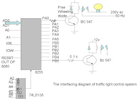
The above figure shows the interfacing diagram to control 12 electric bulbs. Port A is used to ontrol lights on N-S road and port B is used to control lights on W-E road. Actual pin connections are listed in table below.
Pins | Light | Pin | Light |
PA0 | R1 | PB0 | R3 |
PA1 | Y1 | PB1 | Y3 |
PA2 | G1 | PB2 | G3 |
PA3 | R2 | PB3 | R4 |
PA4 | Y2 | PB4 | Y4 |
PA5 | G2 | PB5 | G4 |
I/O map:
Ports/control Register | Address Lines A7 A6 A5 A4 A3 A2 A1 A0 | Address |
Port A Port B Port C Control Register | 1 0 0 0 0 0 0 0 1 0 0 0 0 0 0 1 1 0 0 0 0 0 1 0 1 0 0 0 0 0 1 1 | 80 H 81 H 82 H 83 H |
Software needed for Traffic Light control
Control word for initialization of 8255.
BSR/IO | MODE A | PA | PCH | MODE B | PB | PCL |
1 | 0 0 | 0 | X | 0 | 0 | X |
= 80 H
I designed a table to show you the data bytes to be sent for specific combinations
For port B output
To glow | PA7 | PA6 | PA5 | PA4 | PA3 | PA2 | PA1 | PA0 | Port A output |
R1,R2,G3 AND G4 | X | X | 0 | 0 | 1 | 0 | 0 | 1 | 0H |
Y1, Y2, Y3 AND Y4 | X | X | 0 | 1 | 0 | 0 | 1 | 0 | 12H |
R3,R4,G1 AND G2 | X | X | 1 | 0 | 0 | 1 | 0 | 0 | 24H |
Source program for Traffic Light Control Using Microprocessor 8255
MVI A,80H --------------------initialize 8255, port A and port B
OUT 83H(CR)-----------------in output mode
START : MVI A, 09H
OUT 80H (PA)----------------send data on PA to glow R1 and R2
MVI A,24H
OUT 81H (PB)----------------send data on PB to glow G3 and G4
MVI C,28H--------------------Load multiplier count (40 10) for delay
CALL DELAY----------------Call delay subroutine
MVI A, 12H
OUT (81H) PA----------------send data on port A to glow Y1 and Y2
OUT (81H) PB----------------Send data on port B to glow Y3 and Y4
MVI C, 0AH-------------------Load multiplier count (10 10) for delay
CALL DELAY----------------call delay subroutine
MVI A, 24H
OUT (80H) PA----------------Send data on port A to glow G1 and G2
MVI A, 09H
OUT (81H) PB--------------send data on port B to glow R3 and R4
MVI C, 28H----------------- Load multiplier count (40 10) for delay
CALL DELAY-------------- call delay subroutine
MVI A, 12H
OUT PA---------------------- send data on port A to glow Y1 and Y2
OUT PB---------------------- Send data on port B to glow Y3 and Y4
MVI C, 0AH----------------- Load multiplier count (10 10) for delay
CALL DELAY-------------- call delay subroutine
JMP START
Delay Subroutine:
DELAY: LXI D, Count -----------Load count to give 0.5 sec delay.
BACK : DCX D --------------------------Decrement counter
MOV A,D
ORA E----------------------------------check whether count is 0
JNZ BACK ----------------------------if not zero, repeat
DCR C --------------------------------- check if multiplier zero, oherwise repeat
JNZ DELAY
RET ------------------------ return to main program.

