Friday, May 27, 2011

Cascade Control System

It there is more than one control systems are added together in a process the control system is called cascade control system.

Block diagram of cascade control system


The inherent interaction that occurs between two control systems in many applications is used in one control loop determined by measurement of a different variable for which interaction exists.


block diagram of cascade control system


Two measurements are taken from the system. Each is used in its own control loop. Set point of inner loop is decided by controller output of outer loop. Cascade control provides better control of the outer loop variable than is accomplished through a single variable system.

cascade control system process
Example of Cascade control system

The temperature controller generates the correction signal based on the actual temperature. This correction signal is used as the set point input to a flow controller. The flow controller signal positions the control valve, which regulates the flow of hot liquid from the vessel.

example of cascade control system
If temperature of heating tank fluid rises above the set point the temperature controller generates pneumatic signal which acts as the set point to the flow controller. Flow controller closes the control valve that decreases the flow of heating fluid so as to get the desired heating effect. Similarly the heating fluid temperature falls below the desired heating effect.

Advantages of cascade control system


The flow controller is much faster than the temperature controller due to much shorter dead time in the secondary loop than in the original single loop system.

The temperature controller with an integral mode remains in the design to ensure zero for all disturbance source.

Thursday, May 26, 2011

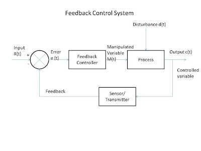
Feedback control system or closed loop control system

There are number of techniques used for process control system that are useful in the analysis and design of modern process control system. Feedback control system is a type used in this type of control system.
In this feedback control system output is measured and compared with input reference signal. The deviation (error) between the two is used by the controller which will send the output so that error of system becomes zero.

feedback-control-system


In this example, feedback control system can be explained. In which the output Ca is continuously measured using level sensor and feedback to be compared with input (desired, set (or) reference) level Cd. The error e= (Cd-Ca) is used to adjust the control value by means of an actuator.

level control system


Advantage of feedback control system


It is very simple technique that compensates for all disturbances
The controller adjusts the controlled variable (affected by the disturbance) with the set point (reference).
The feedback control loop does not care for the disturbance entering into the process. It tries only to minimum the value of error by compensating for all disturbances.

Disadvantage of feedback control system


It does not take corrective action until after the disturbance has upset the process and generates an error signal.
The feedback controllers continue changing its output until measurement and set point are in agreement.
It solves the problems by trial and error method and thus causes oscillatory response of a feedback loop.

Saturday, May 21, 2011

Optical Torsion meter

Basic Principle

Due to torque, an angular twist (angular displacement) occurs on the shaft between its ends. This angle of twist is measured by using optical means where in angular deflection of light rays is proportional to twist and hence the torque.


Construction of optical torsion meter
optical torsion meter

The main parts of an optical torsion meter as follows:

A shaft is used on which two casting M and N are connected at a known distance.
A tension strip linking the two castings.
Two mirrors which are fitted and aligned on the castings.
A light beam falling on the mirrors, an optical system and a torque calibrated scale.

Operation of optical torsion meter

When the shaft is transmitting torque, a relative movement occurs between castings M and N, and due to this, the mirrors will change position ( partial inclination between the two mirrors) since they are attached to the castings.

As the mirrors are constantly made to reflect a light beam on the torque calibrated scale, due to the changed position of the mirrors, there will be an angular deflection of the light rays which is measured from the calibrated scale.

This angular deflection of the light rays is proportional to the twist on the shaft (relative movement of casting M and N) and hence the torque of the shaft.

Applications of optical torsion meter

It is used in steam turbines and I.C engines

Friday, May 20, 2011

Mechanical Torsion Meter

Mechanical torsion meter is used to measure torque developed by a machine.

Basic principle of mechanical torsion meter


When a shaft is connected between a driving engine and driven load, a twist (angular displacement) occurs on the shaft between its ends. This angle of twist is measured and calibrated in terms of torque.

Construction of mechanical torsion meter


The main parts of the mechanical torsion meter are as follows:

  1. A shaft which has two drums and two flanges mounted on its ends as shown in the diagram.
  2. One drum carries a pointer and other drum has a torque calibrated scale.
  3. A stroboscope is used to take readings on a rotating shaft.

Operation of mechanical torsion meter:


  1. One end of the shaft of the torsion meter is connected to the driving engine and its other end to the driven load.
  2. An angle of twist is experienced by the shaft along its length between the two flanges which is proportional to the torque applied to the shaft.
  3. A measure of this angle of twist becomes a measure of torque when calibrated.
  4. The angular twist caused is observed on the torque calibrated scale corresponding to the position of the pointer. As the scale on the drum is rotating, reading cannot be taken directly. Hence a stroboscope is used. The stroboscope’s flashing light is made to fall on the scale and the flashing frequency is adjusted till a stationary image is obtained. Then the scale reading is noted.

Application of mechanical torsion meter


  • Simple and inexpensive method
  • Power of shaft can be calculated (flashing frequency gives information about speed).

Limitation of mechanical torsion meter


Poor accuracy due to small displacement of the pointer.
Sensitivity is reduced even due to small variation in speed.
It can be used only on shafts rotating at a constant speed.

Thursday, May 19, 2011

Polytechnic Results 2011 for Andhra Pradesh

Check out the below form to find your polytechnic results in 2011. The results shown in this page is directly brought to you by the official website.

you can download the CEEP-2011 rank from these below websites.
www.ceep.ap.nic.in, www.sbtetap.ac.in, www.dteap.ac.in, www.sbtetap.gov.in Www.manabadi.com, www.schools9.com

If you have any doubts and troubles in viewing  the result, please use the comments form, so that i can help you as soon as possible. STATE BOARD OF TECHNICAL EDUCATION AND TRAINING, GOVT. OF A.P.Results are below.

http://203.153.32.182/ceep2011/ceep_results.htm

Best of Luck Students

Friday, May 13, 2011

List of Instrumentation and Control Engineering Companies in India

I have prepared a list of instrumentation and control engineering based companies in India, which you should must know.


National Instruments:

National Instruments transforms the way engineers and scientists around the world design, prototype, and deploy systems for test, control, and embedded design applications. Using NI open graphical programming software and modular hardware, customers at more than 30,000 companies annually simplify development, increase productivity, and dramatically reduce time to market. From testing next-generation gaming systems to creating breakthrough medical devices, NI customers continuously develop innovative technologies that impact millions of people.

If you are interested in this company you may send a mail to ni.india.resumes@ni.com.

ABB:

ABB is a global leader in power and automation technologies that enable utility and industry customers to improve their performance while lowering environmental impact.

Go to the Careers Section to Search Jobs

Larsen & Tourbo:

Larsen & Toubro Limited (L&T) is India's largest engineering and construction conglomerate with additional interests in electricals, electronics and IT. A strong customer-focus approach and constant quest for top-class quality have enabled L&T to attain and sustain leadership over 6 decades.

Website :  http://www.larsentoubro.com/
Instrumentation and control Jobs in Larsen & Tourbo here 

Robert Bosch

Robert Bosch is leading manufacture of automobile Instruments. Robert Bosch and Mico are jointly working in India.

Site Url :www.boschindia.com

Invensys

Designer and supplier of digital signal processing solutions and semiconductor products. Includes corporate and investor data, products, and employment.

website : www.invensys.com

GE

From jet engines to power generation, financial services to plastics, and medical imaging to news and information, GE people worldwide are dedicated to turning imaginative ideas into leading products and services that help solve some of the world's toughest problems.

website : www.ge.com

Suzlon

Suzlon Energy is Asia's strongest growing fully integrated wind power company and ranks amongst the top ten in the world. Suzlon integrates consultancy, design, manufacturing, operation and maintenance services to provide customers with total wind power solutions.

website : www.suzlon.com

Apna Technologies

ApnaTech is on the constant lookout for Intrepreneurs who are Excited about Personally Building a GREAT Organization and who can think miles ahead while focused on EXECUTING what they are doing right now with concrete understanding of the basics and passionate in Core Engineering.

Website : http://www.apnatech.com/careers
Drop in your resume to careers@apnatech.com

Whirlybird


Whirlybird Electronics was founded to establish a benchmark in the field of unmanned aerial vehicles (UAV) and unmanned ground vehicles (UGV). Our primary domain is Avionics with indigenous development of Inertial Navigation Systems (INS).

Website : http://www.whirlybird.in/index.html

Please checkout the list of various opening below & to apply, mail your resumes to: careers@whirlybird.in

ESSAR

Committed to innovative growth, Essar Group speaks the new language of success. The Group is judiciously invested in the commodity, annuity and services businesses

Website : http://www.essar.com/

be a part of the Essar family? careers@essar.com

Tuesday, May 3, 2011

Resistors and Types of Resistors

A very basic component that all the engineers including instrumentation discipline should know about. A resistor is a passive component. It introduces resistance. Resistance is defined as the property of the material which opposes the flow of current. Since the resistors have no polarity they can be connected in the circuit in either direction.

R = (PL)/A

Where, R = Resistance (W)
L = Length of the conductor (m)
A = Area of cross-section of conductor (m^2)
P = Specific resistance or resistivity of the material.

This resistance value of a resistor depends upon physical dimensions of the resistor and resistivity of the conducting material used.

Resistors are used in electronic circuits to:


  1. Limit the flow of current
  2. Provide load
  3. Produce a desired voltage drop.
  4. To control gain
  5. Fix time constants etc.,


Types of resistors

Resistors are broadly classified into two types on the basis of the nature of value of resistance.

  1. Fixed resistor
  2. Variable resistor.

The below image is a chart on the types of resistors, click on it to enlarge.


Fixed resistor

The fixed resistors are further classified into two types. They are

  1. High stability type
  2. General Purpose type


High stability type

High stability types are further classified into four types


  1. Cracked carbon resistors
  2. Metal film resistors
  3. Metal oxide resistors
  4. Wire wound resistors


General Purpose type

Carbon composition resistors are called general fixed resistors. They are two types.


  1. Solid cylindrical types
  2. Film types


Solid cylindrical type is divided into two types


  1. Un- Insulated molded type
  2. Insulated molded type


General purpose variable resistors

This is divided into three types


  1. Carbon composition variable resistors
  2. Wire Wound Variable resistors
  3. Precision type variable resistors


Precision type variable resistors

This is subdivided into


  1. Precision variable potentiometers
  2. Trimming potentiometers


Precision variable potentiometers
It is divided into two types:

  1. Film types
  2. Wire wound type


Trimming potentiometers

  1. Rectilinear
  2. Rotary
Use the above image to have a clear cut idea on classification of resistors