Sunday, January 30, 2011

How to Measure Flow Using Orifice Meter

In this post, i am interested in covering the details about how to measure flow using Orifice meter. And i am starting it from the scratch.

Basic Principle of Orifice Meter


When an orifice plate is placed in a pipe carrying the fluid whose rate of flow is to be measured, the orifice plate causes a pressure drop which varies with the flow rate. This pressure drop is measured using a differential pressure sensor and when calibrated this pressure drop becomes a measure flow rate. The flow rate is given by.

orifice meter flow rate formula


Where, Qa = flow rate
Cd = Discharge coefficient
A1 = Cross sectional area of pipe
A2 = Cross sectional area of orifice
P1, P2 = Static Pressures

Description of Orifice Meter

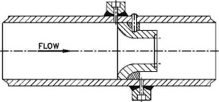
orifice meter diagram

The main parts of an orifice flow meter are as follows:

  • A stainless steel orifice plate which is held between flanges of a pipe carrying the fluid whose flow rate is being measured.
  • It should be noted that for a certain distance before and after the orifice plate fitted between the flanges, the pipe carrying the fliud should be straight in order to maintain laminar flow conditions.
  • Openings are provided at two places 1 and 2 for attaching a differential pressure sensor (U-tube manometer, differential pressure gauge etc) as shown in the diagram.

Operation of Orifice Meter


  • The detail of the fluid movement inside the pipe and orifice plate has to be understood.
  • The fluid having uniform cross section of flow converges into the orifice plate’s opening in its upstream. When the fluid comes out of the orifice plate’s opening, its cross section is minimum and uniform for a particular distance and then the cross section of the fluid starts diverging in the down stream.
  • At the upstream of the orifice, before the converging of the fluid takes place, the pressure of he fluid (P1) is maximum. As the fluid starts converging, to enter the orifice opening its pressure drops. When the fluid comes out of the orifice opening, its pressure is minimum (p2) and this minimum pressure remains constant in the minimum cross section area of fluid flow at the downstream.
  • This minimum cross sectional area of the fluid obtained at downstream from the orifice edge is called VENA-CONTRACTA.
  • The differential pressure sensor attached between points 1 and 2 records the pressure difference (P1 – P2) between these two points which becomes an indication of the flow rate of the fluid through the pipe when calibrated.

Applications of Orifice Meter


  1. The concentric orifice plate is used to measure flow rates of pure fluids and has a wide applicability as it has been standardized.
  2. The eccentric and segmental orifice plates are used to measure flow rates of fluids containing suspended materials such as solids, oil mixed with water and wet steam.

Advantages of Orifice Meter


  1. It is very cheap and easy method to measure flow rate.
  2. It has predictable characteristics and occupies less space.
  3. Can be use to measure flow rates in large pipes.

Limitations of Orifice Meter


  1. The vena-contracta length depends on the roughness of the inner wall of the pipe and sharpness of the orifice plate. In certain cases it becomes difficult to tap the minimum pressure (P2) due to the above factor.
  2. Pressure recovery at downstream is poor, that is, overall loss varies from 40% to 90% of the differential pressure.
  3. In the upstream straightening vanes are a must to obtain laminar flow conditions.
  4. Gets clogged when the suspended fluids flow.
  5. The orifice plate gets corroded and due to this after sometime, inaccuracy occurs. Moreover the orifice plate has low physical strength.
  6. The coefficient of discharge is low.

Note: the materials used for maintaining orifice plate are stainless steel, phosper bronze, nickel and monel.

Sunday, January 23, 2011

Microprocessor Based Traffic Light Control Project

Designing a microprocessor system to control traffic lights is discussed in this post. The traffic light arrangement is as shown in the figure. The trffic should be controlled in the following manner.

Allow traffic from W to E and E to W transition for 20 seconds.
Give transition period of 5 seconds (yellow bulbs ON)
Allow traffic from N to S and S to N for 20 seconds.
Give Transition period of 5 seconds (yellow bulbs ON)
Repeat the process.

Friday, January 21, 2011

Electromagnetic Flow meter

A video about Working of Electromagnetic Flow meter.


Updated Video on Electromagnetic flow measuring principle


Thank for Watching, any comments???

Thursday, January 20, 2011

Head type flowmeters – Based on Differential Pressure Measurement

In these head type flowmeters, some devices is inserted into a pipe carrying fluid. It obstructs the flow of fluid and creates a pressure difference on either side of the device. The most commonly used devices are as follows:

  1. Orifice plate.
  2. Venture plate.
  3. Flow nozzle.
  4. Doll flow tube.
  5. Pilot tube.
The basic principle of all such devices is that due to obstruction, the velocity of the fluid increases and the pressure decreases. Then the volume flow rate is proportional to the square root of pressure difference across the obstruction. To measure pressure difference, diaphragm based differential pressure transducer is used.

Orifice plate:

orifice plate construction
The orifice plate is a metal disk with a concentric hole as shown in the figure below. It is the simplest device used in almost all industrial application because of cheapness and availability in wide range of sizes.

There are certain limitations of the orifice plate. For very high flow rates, the permanent pressure losses are very high. Over a period of time, the sharp edge of the hole wear out and the particles in the flowing fluid build up behind the hole reducing diameter. Hence discharge coefficient gradually changes. This problem can be eliminated by using eccentric hole near the bottom of the pipe which sweeps out built-up particles behind the plate. Sometimes bubbles of vapour or gas tend to built up behind plate and obstruct the flow. This can be avoided by mounting the orifice plate in vertical run of the pipe.

Flow nozzle:

flow nozzle of construction
As compared to the orifice plate, flow nozzle is better option as no possibility of solid particles or bubbles of gas sticking in the flow restriction. The flow across nozzle is as shown in the figure below.

The measurement accuracy of the flow nozzle is very high as no harm of getting warned out. But the cost is comparatively higher as fabrication of the flow nozzle is difficult. Also permanent pressure losses are also high similar to the orifice plate. The flow nozzles are typically used for the steam flow measurement.

In the next post i will discuss about venturi plate, doll flow tube, pilot tube.

Friday, January 14, 2011

Instrumentation Project Titles


A list of Instrumentation related Project Topics are available here, if you need any contents related to the topic, please use the comment box.

Pc Based 8 Channel Thermo Couple Simulators And Evaluator
Continuous Monitoring Of Metabolic Activity System For Organ Preservation
Computer Based Dual-Beam Colorimeter
Microprocessor Based Instrument to detect And Control Gaseous Exhaust Pollutants
Rotomatic Channel Selector
Ultrasonic Flow Detector
Pc Based Process Control
Pc Based Industrial Sequence Control System
Pc Based Determination Of Thermal Properties Of Food
Pc To Pc Wireless Communication Using In Real Oic In Real Time With File Transfer
Pic Microcontroller Based Wind Speed And Direction Monitoring System
Air Flow Control Using Fuzzy Logic
Microcontroller Based Moisture Meter
Automated Ambulance Detection and Gate Control
Data Acquisition Using Zigbee Technology

Thursday, January 6, 2011

Bimetallic Strip

Here a video related to Bimetallic Strip, since my visitor Ahamd Zeeshan requested in my new chat roll box..
Use my chatroll box to contact me..

Sunday, January 2, 2011

Flow Measurement Devices

The important instruments used to measure flow have been listed below:


Secondary or rate meters
Head Type Flow Meters
Obstruction meters


Pitot tube (Total Pressure Probe)


Special Methods


I will be discussing all of these devices listed above, if you need to know about any device, please use comment box or chat box.

Saturday, January 1, 2011

How to Measure Flow using Magnetic Flow Meter

Basic principle:

When a flowing conducting fluid is subjected to a transverse magnetic field, the flowing conducting fluid cuts the magnetic field and causes a voltage to be induced. This induced voltage is proportional to the fluid velocity, that is, flow rate.

Construction of Magnetic flow meter:

magnetic flow meter

The main parts of this instrument are as follows:

A conducting fluid is flowing through a non-magnetic and non-conducting pipe, whose flow rate is to be measured.

Two electrodes are attached in opposite sides of pipe carrying the conducting fluid. These electrodes are in contact with the flowing conducting fluid.

The pipe is surrounded by an electromagnet which produces which produces a magnetic field.
magnetic flow meter

Operation of a Magnetic Flow Meter:


This magnetic flow meter is based on farady’s law of induced voltage which is given as follows,

E = BLV
Where,
E = induced voltage(volts)
B = flux density (gauss)
L = Length of conductor which is the diameter of the pipe (cm)
V = Average velocity of conductor (fluid) in cm/sec

When the conducting fliud flows through the pipe which is subjected to a magnetic field, the conducting fluid cuts the magnetic field and due to this a voltage is induced. As the magnetic field is constant, voltage obtained across the electrodes will be directly proportional t average fluid velocity and diameter (length) and hence becomes a measure of volume flow rate.

Applications of a Magnetic Flow Meter:


Used to measure flow rates of conducting fluids.
Used to measure flow rates of slurries, corrosive and abrasive fluids.
Magnetic flow meter is used to measure bidirectional flows by reversing connections which can be done automatically.

Advantages of magnetic flow meter


These meters do not cause obstruction to flow and hence cause no pressure drop.
For measurements, it does not matter whether the flow is laminar or turbulent.
It gives accurate results.
Its reliability is high, that is, it gives a standard performance for an elongated period of time.
It can handle greasy materials and fluids containing suspended solids.
The measurement is independent of viscosity, density, temperature and pressure.

Limitations of Magnetic Flow Meter:


The fluid whose flow rate is to be measured should satisfy certain conduction conditions.
The fluid should be full in the pipe to get accurate results.
Air and gas bubbles in the fluid will cause errors.
When certain fluids, the electrodes might get coated with scales and this will affect the output signal. However, this can be taken care off by cleaning the electrodes.
In many cases, the output voltage is low and hence requires amplification.

How to Calibrate a Thermometer using Primary Calibration Method

The temperature measuring deices such as mercury-in-glass thermometer, bimetallic thermometer, resistance thermometer and thermocouples can be calibrated using a primary calibration method.

In this method, the introduced accurately known samples of the variable are the ice point and steam point. Using this ice point and steam point, the instrument is checked, set and thus calibrated. As the instruments (thermometers) are calibrated with reference to the equilibrium temperature of substances, it is primary calibration.

To set the ice point, the sensing element (bulb) and the stem of the instrument (thermometer) is surrounded with a mixture of crushed ice and water which is open to atmosphere. Now the instrument will show some indication on its scale and this is taken as ice point (zero point) on the scale of the instrument.

Now to set the steam point (as shown in the diagram), the instrument’s sensing element (bulb) and the stem is surrounded by steam to its full depth. Care should be taken to see that the instrument doesnot contact the boiling water. Now the instrumentwill show some indication on its scale and this is taken as the steam point (100’C) on the scale of the instrument.

Thus by giving known temperature inputs (ice point and steam point), the instrument’s (thermometer’s) response is noted and calibrated.